Why do most large wind turbines today choose to use doubly-fed induction generators (DFIG)? In the field of wind power generation, efficiency, cost, and grid performance are key considerations. With its unique advantages, the doubly-fed induction generator has gradually become the mainstream solution.

What Is A Doubly Fed Induction Generator?
A doubly-fed asynchronous wind turbine generator (DFIG, Doubly-fed Induction Generator) is a type of wound-rotor induction generator.

The stator of the doubly-fed generator is directly connected to the grid, while the wound rotor is connected to the grid through a converter. When the load and speed of the generator change, the frequency and phase of the current fed into the rotor winding are adjusted by the converter, so the voltage and frequency of the stator output remain stable.
Structure Of The DFIG Wind Turbine Generator
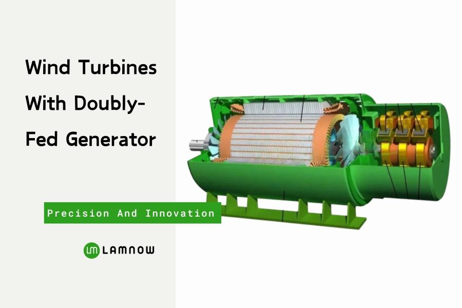
The generator mainly consists of the motor body and the cooling system. The motor body is composed of the stator, rotor, and bearing system, and the cooling system includes three types: water cooling, air-air cooling, and air-water cooling.

The structure and composition of the doubly-fed generator are the same as those of a wound-rotor induction motor, with the main difference lying in the electromagnetic design requirements of the generator.
A doubly-fed wind generator usually adopts 4 poles or 6 poles. Generators below 2MW mostly use 4 poles, and generators above 2MW mostly use 6 poles. This section introduces the stator and rotor structure of a 4-pole generator.
Stator
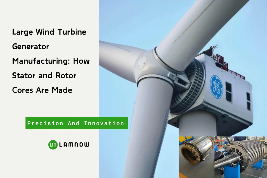
Stator Core
We stack silicon steel sheets with high magnetic permeability (usually cold-rolled non-oriented electrical steel) to form the stator core and create a magnetic circuit. They generally use silicon steel sheets with a thickness of 0.5 mm, 0.65 mm, or thinner 0.35 mm, and they apply an insulating coating on the surface to reduce eddy current losses.

The slot shape of the core is designed according to the winding form, ensuring a good slot fill factor while considering both electrical and mechanical strength.
For stator laminations with an outer diameter of 1000 mm or less, laser cutting, compound stamping, or single-slot punching is used. For laminations with an outer diameter above 1250 mm, a segmented design is usually adopted and produced by stamping.

The laminations are stacked with tooling, and some stator cores require ventilation plates to improve heat dissipation.
The outer circle of the stator core usually needs to be turned on a lathe to ensure roundness and dimensional accuracy.
Stator Winding
The slots of the stator core contain three-phase AC windings. The windings form 4 poles and connect in a star configuration. When a three-phase AC power supply energizes the windings, they generate a rotating magnetic field in the stator.

The windings are usually made of copper conductors, including round wires and flat wires.
The doubly-fed generator often uses a multi-layer overlapping winding process to make the coils tightly arranged in the slots, improving current-carrying capacity and heat dissipation.
The insulation level of the winding is generally class F or class H, which meets the high-temperature requirements of long-term operation of wind turbines.
The winding ends are fixed with binding, supports, and insulating sleeves to ensure they do not loosen under electromagnetic force and mechanical vibration.
Stator Assembly
The wound stator is usually fixed inside the frame using a press or similar equipment. The housing has ventilation holes for heat dissipation.
Rotor
Rotor Core
The rotor core is made by stacking electrical silicon steel sheets. The common thickness is about 0.35 mm, 0.5 mm, or 0.65 mm, manufactured by stamping or laser cutting.

The core is fixed with pressing plates, tie rods, or end rings during stacking to ensure mechanical strength.
Rotor Winding
Unlike the traditional squirrel-cage rotor, the doubly-fed generator adopts a three-phase symmetrical winding.
The rotor windings are embedded in the slots of the rotor core, wound as 4-pole three-phase AC windings, and connected in a star configuration. When connected to a three-phase AC supply, a rotating magnetic field is generated around the rotor core.

The windings are usually made of enameled copper wire and embedded in semi-closed or open slots. This design facilitates coil insertion while maintaining good electromagnetic performance.
The winding ends are reinforced with binding tape and insulation after protruding from the core, ensuring no loosening or short circuits during operation.
Regardless of the number of stator or rotor slots, the pole number of the stator windings must be the same as that of the rotor windings.
Rotor Shaft
Three slip rings are installed on the shaft. The slip rings are insulated from each other and from the shaft. The three leads of the rotor windings are connected to the slip rings through grooves in the shaft. Two axial fans are installed on the shaft to cool the generator.
Rotor Installation
The technician installs the rotor inside the stator, and the end covers on both ends of the frame support it. The end covers hold the bearings. On the slip ring side, the assembler installs a brush holder, and springs press three carbon brushes tightly against the slip rings.
Other Parts
The generator has two terminal boxes. The main terminal box on the frame connects the stator winding leads. The terminal box on the brush holder connects the rotor winding leads through the slip rings. Several ventilation holes are on the upper housing for cooling.
Cooling Of The Doubly-Fed Generator
The heat generated by the stator and rotor is dissipated by air cooling. Airflow is driven by axial fans at both ends of the rotor. The orange-red arrows in the diagram indicate the airflow path. Part of the air flows through the stator and rotor windings for cooling and is then discharged. Another part enters through the rotor support, passes through the stator and rotor cores, and is discharged after cooling them.

Wind turbines operate in dusty environments, so engineers must filter the cooling air. The generator has an air filter installed on top. For larger generators, operators use an external heat exchanger to forcibly cool the circulating air. Designers may choose either an air-cooled or water-cooled heat exchanger.
A centrifugal fan of the cooler pushes in external air. The cooler isolates the external air from the internal cooling air, and the heat exchanger transfers heat between them. The outlet discharges the heated external air, while the cooling air circulates only between the generator and the cooler.
Why more and more wind turbines adopt DFIG?
Compared with the full-power converter scheme, the doubly-fed solution only needs partial power electronic devices, significantly reducing cost. At the same time, it can flexibly adjust active and reactive power, supporting stable grid operation. Therefore, DFIG has become the preferred solution for large-scale wind farms.
Wind Turbine – Choose Lamnow
We have many years of experience in manufacturing motor cores and can produce generator cores with a maximum outer diameter of 2170 mm. Lamnow usually uses laser cutting, skewed slotting, and compound stamping to produce wind power laminations. The cores are stacked by gas-shielded welding. In addition, horizontal and vertical lathes are used for machining the outer diameter of the cores.

If you have requirements for wind turbine cores, feel free to contact us anytime.


