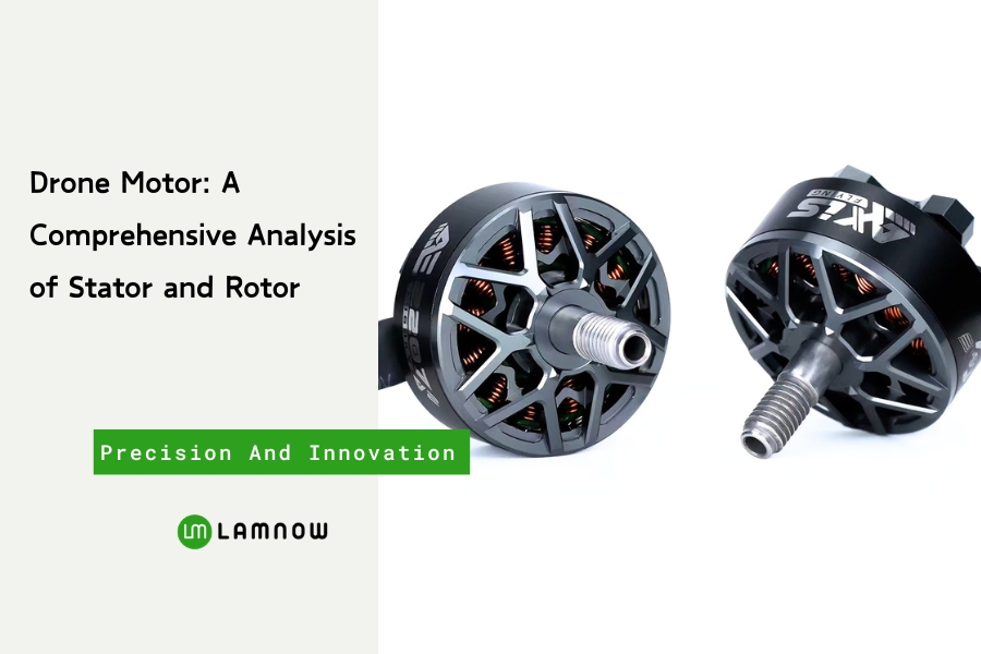
What ultimately dictates a drone’s flight performance? Without a doubt, it is the drone motor.
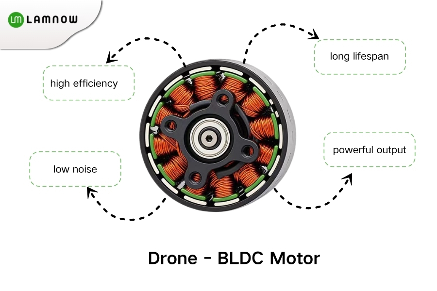
Most mainstream drones today utilize brushless motors. These are favored for their high efficiency (exceeding 80%), long lifespan, low noise, and powerful output; they require an electronic speed controller (ESC) to operate. Such motors are the standard for both consumer and industrial-grade drones.
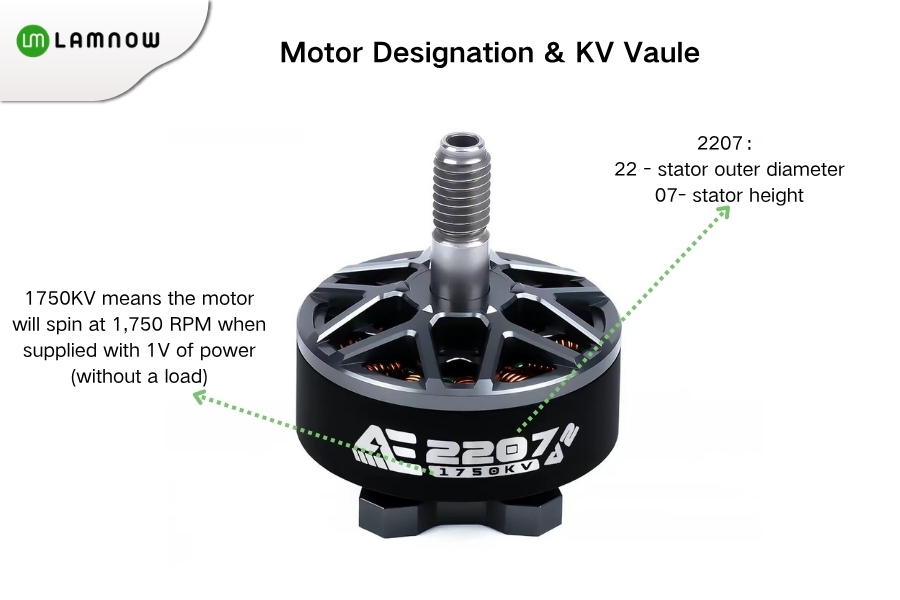
Motors are typically marked with a string of characters. Beginners often struggle to interpret these, which can lead to purchasing the wrong model. Let’s look at a common example: 2207 1750KV.
Motor Designation:
The four-digit code (XXXX) represents the stator’s outer diameter and height (in millimeters). In this case, “22” is the stator’s outer diameter, and “07” is its height.
KV Rating:
The KV rating indicates how many revolutions per minute (RPM) the motor will spin for every 1 volt (V) of applied voltage (under no-load conditions).
1750KV means the motor will spin at 1,750 RPM when supplied with 1V of power (without a load).
So, how are motor stators and rotors designed and manufactured? Let’s take a closer look.
Design of Drone Motor Stators and Rotors
While low-cost motors on the market are often created by simply copying blueprints or reverse-engineering existing designs, high-end motors—such as those used for racing or freestyle flying—are developed through iterative optimization based on electromagnetic and structural simulations.
Simulation-based design is the core process that determines a motor’s efficiency, torque, heat generation, and vibration levels; it is also the key reason why motors from reputable manufacturers vastly outperform generic, low-quality alternatives.
In the drone motor industry, the most widely used software for electromagnetic simulation includes MotorCAD and Maxwell (2D/3D). Engineers input parameters such as the stator’s axial and radial dimensions, rotor dimensions, air gap, winding specifications (e.g., wire gauge, number of turns), magnet grade, load conditions, and target KV rating. Through simulation, they analyze electromagnetic and thermal performance, rotational speed, torque, power output, no-load back-EMF, cogging torque, load characteristics, inductance, eddy-current losses, efficiency, and electromagnetic forces.
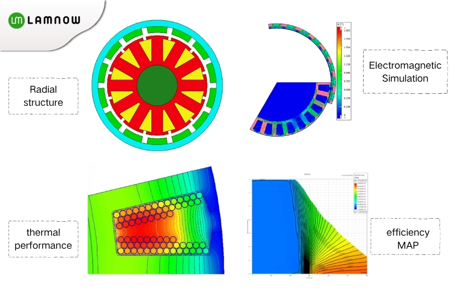
Once the design is finalized through simulation, the definitive mechanical blueprints are established. A complete drone motor typically consists of the following components:
Stator core
Three-phase copper coils
Rotor
Permanent magnets
Bearings
Base
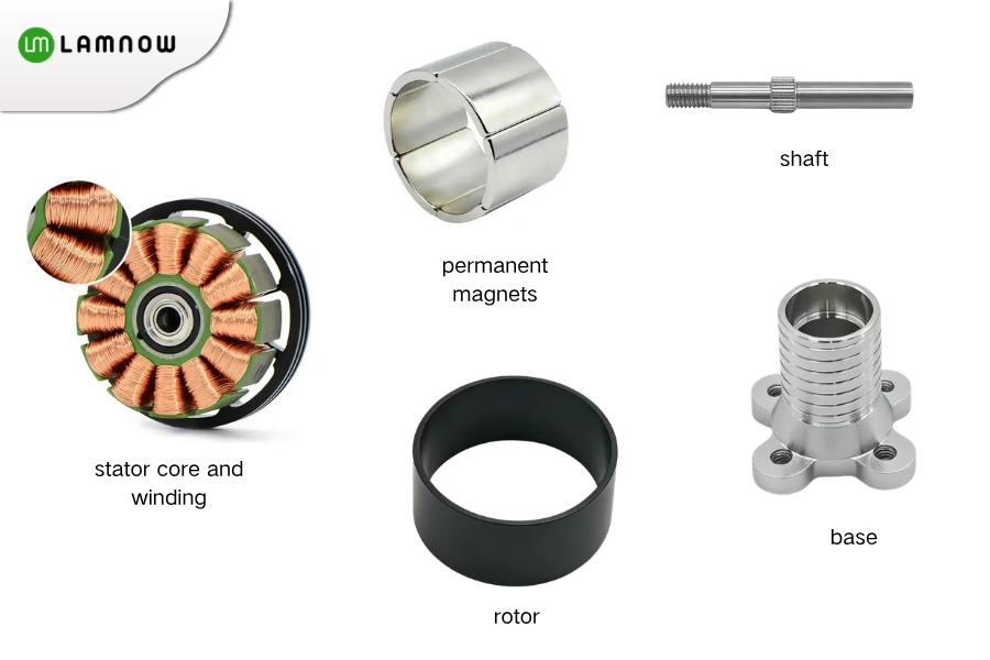
The next phase involves manufacturing the components based on the motor design. Here, we will focus specifically on the production of the stator and the rotor.
Stator Manufacturing Process
Stator Core
UAV stator cores are typically composed of stacked non-oriented electrical steel laminations. Common material brands include Baosteel and Shougang.
Standard lamination thicknesses are 0.2 mm, 0.25 mm, 0.35 mm, and 0.5 mm.
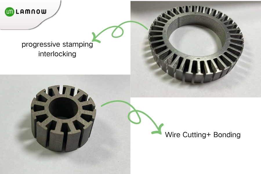
For prototypes, laminations are generally produced using wire-cut EDM or laser cutting, followed by an adhesive bonding process.
For mass production, high-speed stamping and interlocking (riveting/staking) are typically used to manufacture the stator cores. We have a wide range of standard stamping dies available; please feel free to contact us if you have any requirements.
Stator Insulation
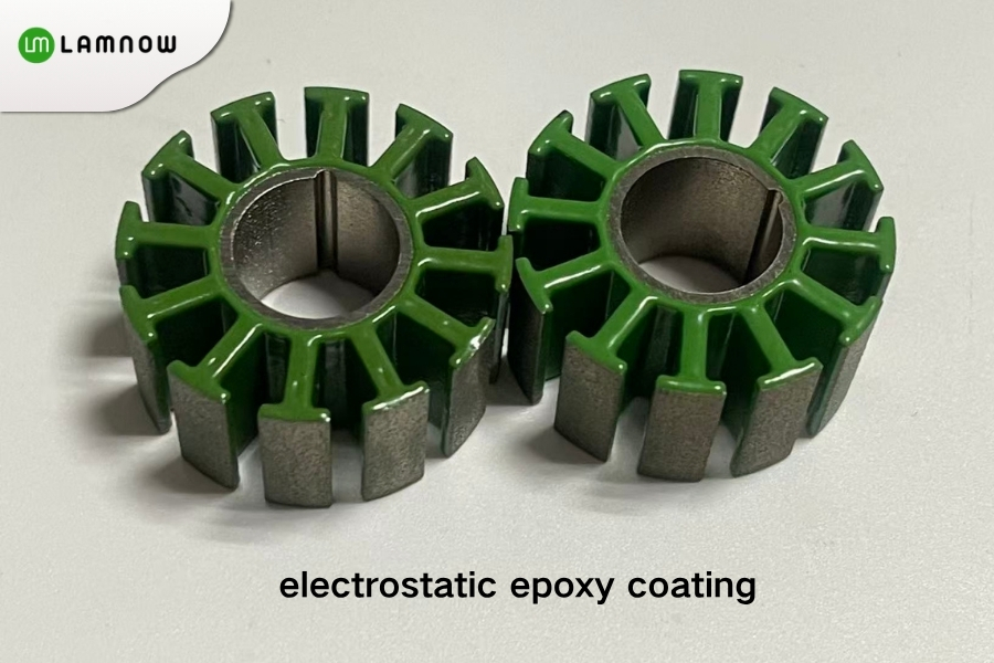
The stator slots are typically insulated using an epoxy coating.
Temperature class: Available in Class F (155°C) and Class H (180°C).
Coating thickness: For prototypes, manual application is generally used, resulting in a thickness of 0.3 mm–0.5 mm per side. For mass production, an electrostatic epoxy coating process is typically employed, yielding a thickness of 0.25 mm–0.35 mm per side.
Coating colors: Green, blue
Stator Winding
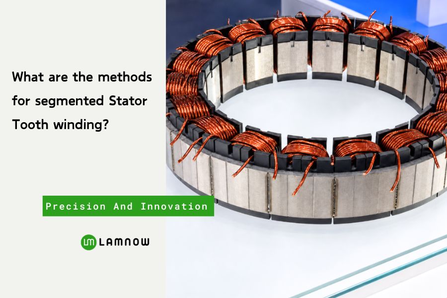
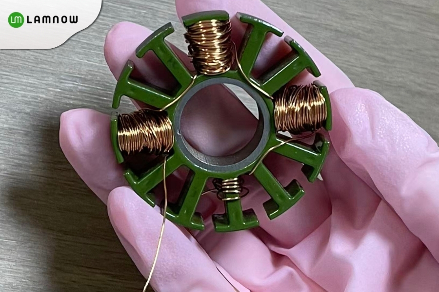
Drone stators typically employ a concentrated winding configuration. In this arrangement, each coil generally wraps around a single stator tooth or occupies a single stator slot.
Common wire diameters range from 0.1 mm to 1 mm.
Depending on the production volume, stator winding can be performed either manually or via automated processes.
Manual winding is primarily used for prototype development, small-batch sampling, or stators with unique structural designs. It relies on jigs and fixtures to assist the operator, offering high flexibility and enabling rapid iteration of different turn-count configurations; however, it suffers from lower production efficiency and requires a high level of operator skill.
Automated winding utilizes “flyer” or needle-type winding equipment to precisely wrap enameled wire around the stator teeth according to specified turn counts and tension settings. This method ensures consistent turn counts and stable slot-fill factors, making it ideal for large-scale mass production. It effectively minimizes human error and ensures consistent motor performance.
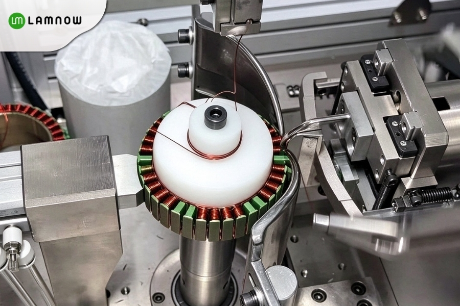
Once the winding process is complete, the stator must undergo testing, which includes:
Hi-Pot (high-potential) testing
Three-phase resistance testing
Inter-turn (turn-to-turn) testing
Insulation testing
Rotor Manufacturing Process
Brushless motor rotors typically employ an external-rotor structure featuring a magnetic ring. The rotor base is generally constructed from either stacked high-permeability silicon steel laminations or an aluminum alloy housing.
Silicon steel laminations are typically fabricated through stamping and interlocking (riveting) processes.
When an aluminum alloy (commonly 6061-T6 or 7075-T5) is used for the housing—processed via precision CNC machining—the uniformity of the wall thickness is critical, as it directly influences the rotor’s dynamic balance.
Permanent Magnets
Neodymium-iron-boron (NdFeB) permanent magnets are the standard choice, with common grades ranging from N35 to N52.
These magnets are first cut and ground to the specified design dimensions, then coated with an anti-corrosion layer to protect against moisture and dust.
The magnets are bonded to the inner wall of the rotor using a high-strength, high-temperature-resistant structural adhesive. They are arranged in an alternating N/S pole configuration and positioned with high precision. Once the adhesive has cured, the magnets undergo a magnetization process.
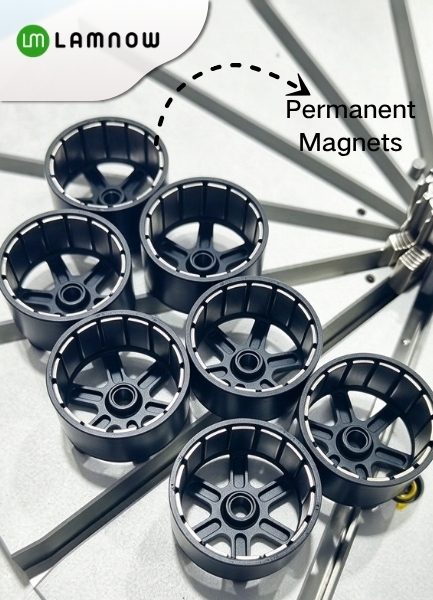
Magnetization is performed using specialized equipment, ensuring uniform magnetic field strength and accurate orientation of the magnetic poles.
The weight and balance of the rotor are of great importance; a high-quality rotor is precisely balanced to ensure smooth, wobble-free rotation, which is essential for the stable flight of a drone.
The performance of a drone motor is never determined solely by its KV rating or power specifications. From the precision of silicon steel lamination and the techniques used for stator winding to the bonding of magnets and the dynamic balancing of the rotor—every single step in the manufacturing process plays a silent yet critical role in ensuring the motor can withstand high-speed flight, intense vibration, and even accidental impacts.
Drone Motor Stator Lamination Core – Choose Lamnow
Lamnow designs and manufactures drone motor laminations in China. We have a public mold for stator core manufacturing. Also, we can provide the customize stator for a new design.
If you need a drone motor core, please contact us.