They are all motors, but why are some used in toy cars while others can drive robots and electric vehicles? What exactly is the difference between common terms such as DC motors, AC motors, stepper motors, servo motors, and linear motors?
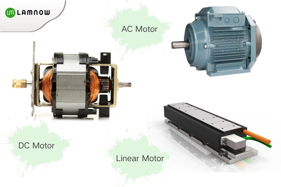
This article will explain, in a simple and easy-to-understand way, several common types of motors used in life and industry applications. It will cover their structural features, working principles, typical applications, and basic ways to distinguish them.
After reading it, you will be able to better understand why a certain type of motor is used in one piece of equipment instead of another.
What Is a Motor?
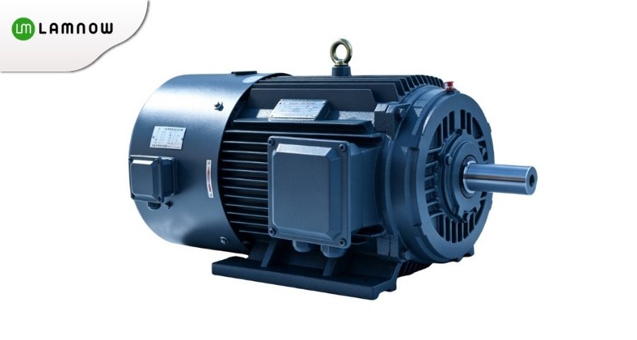
A motor, fully known as an electric motor, is an electromagnetic device that converts electrical energy into mechanical energy. Most rotary motors consist of a stator and a rotor, and they generate torque through the interaction between electric current and a magnetic field. A linear motor, on the other hand, directly produces linear motion.
How Are Motors Classified?
There is more than one way to classify motors. Some are classified by power supply type, such as DC motors and AC motors. Some are classified by commutation method, such as brushed DC motors and brushless DC motors. Others are distinguished by operating principle, control method, motion form, or magnetic flux direction, such as induction motors, permanent magnet synchronous motors, stepper motors, servo systems, linear motors, and axial flux motors.
Therefore, when you are just getting started, there is no need to focus too much on which strict category each motor belongs to. What matters more is understanding three key questions: What does it look like? How does it work? And where is it commonly used? Following this logic, we will break down several of the most common types of motors one by one.
Brushed DC Motor
Structure
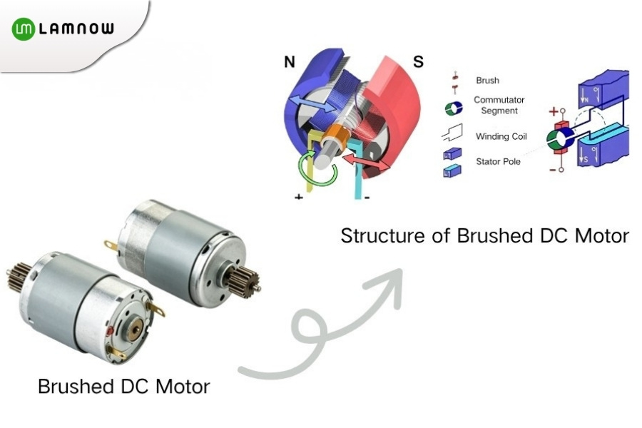
A brushed DC motor usually consists of stator magnetic poles, rotor windings, brushes, a commutator, and an output shaft. Its typical feature is the presence of brushes and a commutator, with the brushes in direct contact with the commutator.
Principle
After power is applied, the brushes and commutator change the direction of current in the rotor windings, allowing the rotor to receive continuous electromagnetic torque and rotate.
Features
- Simple structure and mature production process.
- Generally low manufacturing cost and relatively simple control method.
- High starting torque and easy speed adjustment.
- Brushes and commutator are subject to wear, which limits service life.
- Electric sparks, noise, and electromagnetic interference may occur during operation.
Applications
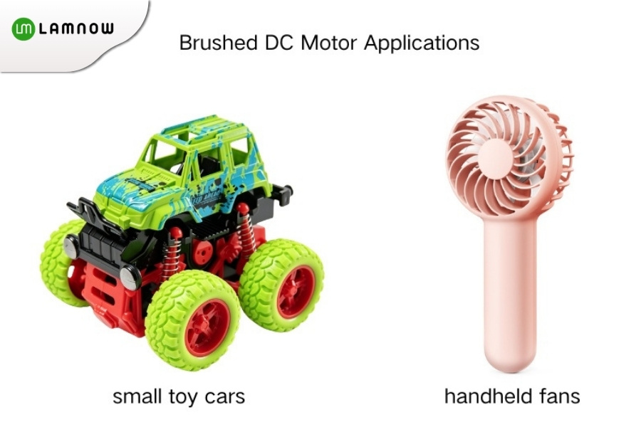
Brushed DC motors are commonly used in low-cost small devices, such as toy cars, small power tools, some electric shavers, and low-cost electric massagers. Their advantages are simple driving and low cost, with no need for complex electronic controllers. Therefore, they are suitable for cost-sensitive applications with relatively low control requirements and less strict requirements for service life and noise.
Brushless DC Motor
Structure
A brushless DC motor, abbreviated as BLDC, commonly consists of stator windings and rotor permanent magnets. It eliminates the brushes and mechanical commutator, and usually requires a matching drive controller.
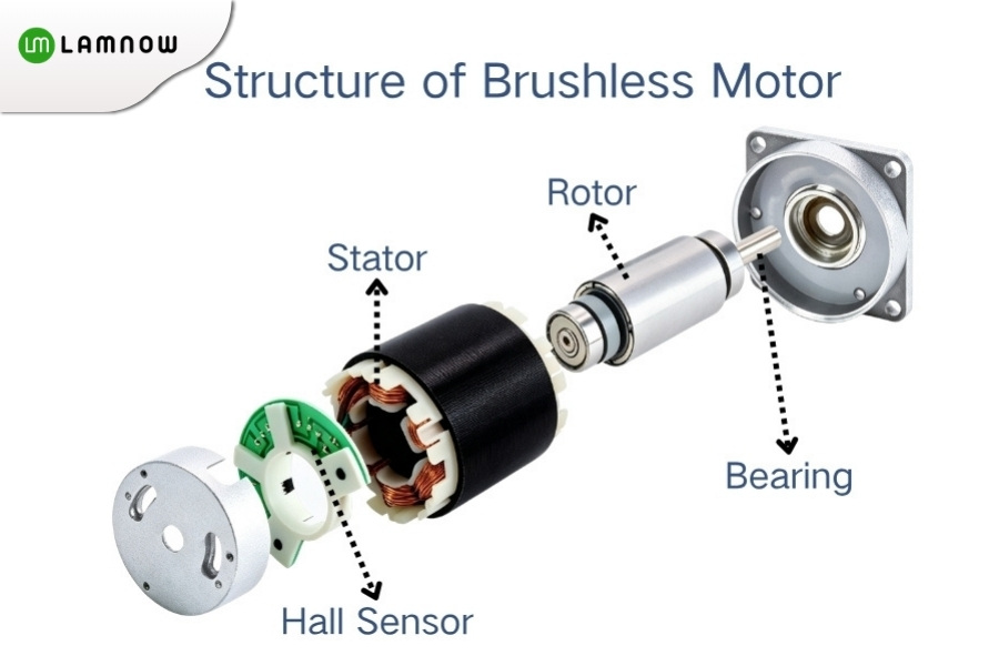
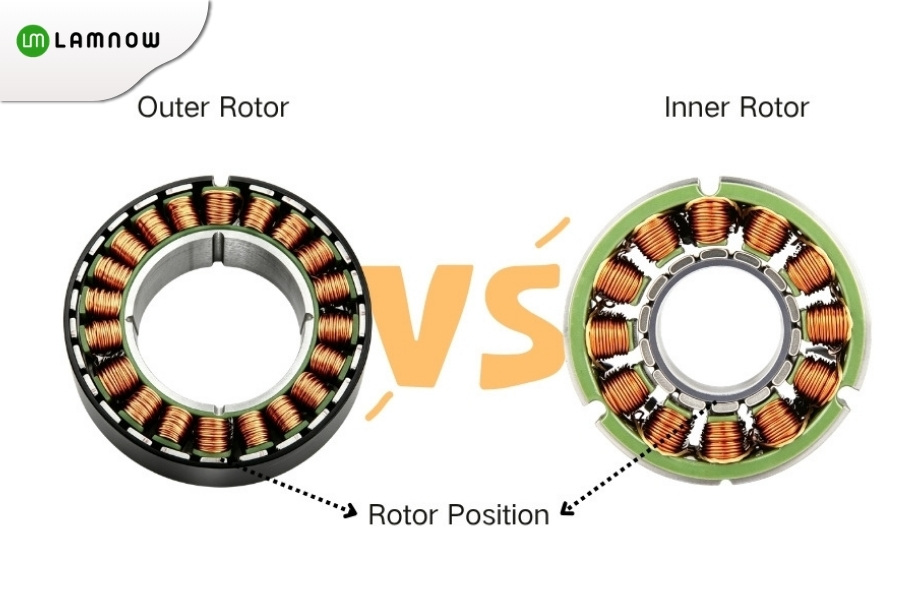
Depending on the rotor position, BLDC motors can be further divided into inner-rotor and outer-rotor types.
Principle
BLDC motor uses a driver to achieve electronic commutation, allowing the stator windings to generate a rotating magnetic field in sequence and drive the permanent magnet rotor to rotate continuously.
Features
- No mechanical wear from brushes and a commutator, resulting in less maintenance.
- Usually higher efficiency, lower noise, and longer service life.
- Inner-rotor motors offer fast response and are suitable for frequent acceleration and deceleration.
- Outer-rotor motors have a larger effective radius, making it easier to achieve higher torque within a similar size.
- A driver is required, so the system cost and control complexity are higher than those of brushed motors.
In practical motor selection, if customers want a longer service life, lower noise, and less maintenance, brushless DC motors are usually considered first. However, they also need to accept the increased driver cost and control complexity.
Applications
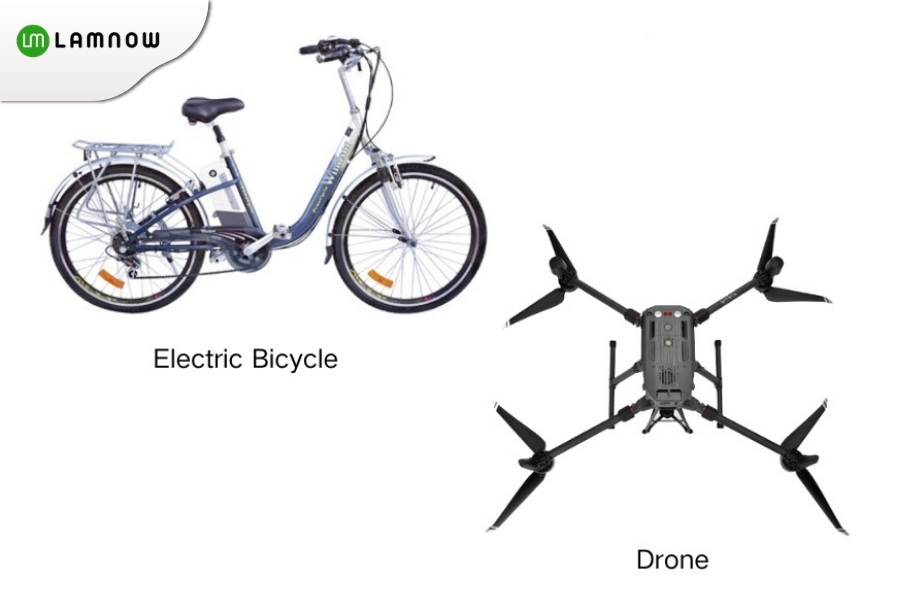
Brushless DC motors are widely used in drones, electric bicycle hub motors, automotive blowers, electronic water pumps, cooling fans, and high-end household fans. For example, the DJI Mini 3 Pro uses 1504C brushless motors. The Hyperdymium digital motor in the Dyson V15 Detect vacuum cleaner and the Direct Drive BLDC motor in LG direct-drive washing machines also reflect the advantages of brushless motors, including high efficiency, low maintenance, and compact structure.
The brushed DC motors and brushless DC motors introduced above are more commonly used in low-voltage DC power supply applications or scenarios that require electronic drive control. Next, we will shift our focus to AC motors. AC motors are widely used in industrial equipment and household appliances, with the induction motor being one of the most representative types.
Induction Motor
Structure
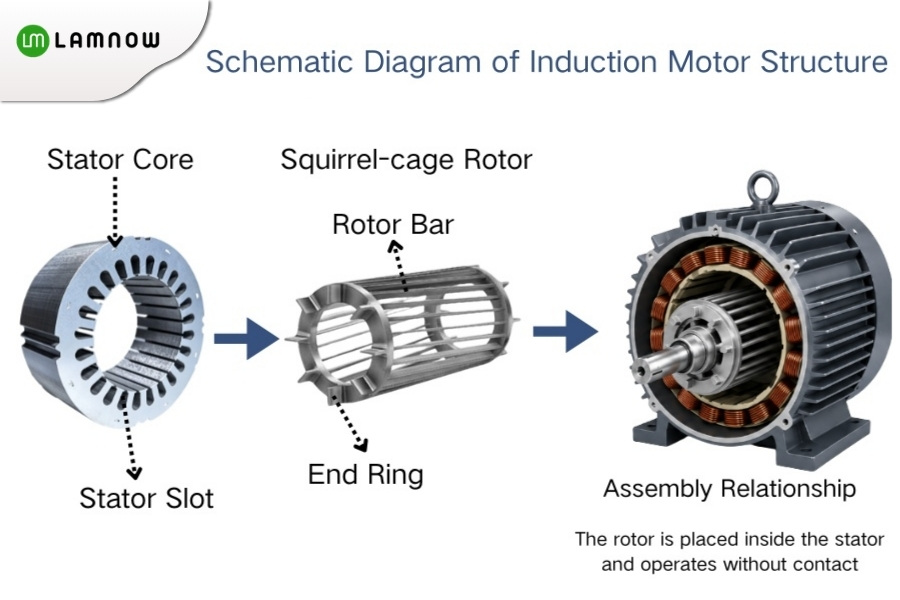
An induction motor, also called an asynchronous motor, commonly consists of a stator core, stator windings, and a rotor. The most common type is the squirrel-cage induction motor, whose rotor is made up of conductive bars and end rings, with a shape similar to a squirrel cage.
Principle
After AC power is supplied to the stator, a rotating magnetic field is generated. This rotating magnetic field induces current in the rotor bars, which in turn produces electromagnetic torque. When operating as a motor, the rotor speed is usually slightly lower than the synchronous speed.
Features
- Mature and reliable structure, suitable for long-term continuous operation.
- Relatively simple maintenance and generally low cost.
- Can be directly connected to AC power for constant-speed operation.
- Usually used with a variable frequency drive when speed control is required.
- Speed adjustment is not convenient under traditional line-frequency operation, and the direct starting current is relatively high.
Applications
Induction motors are a common power source in industrial equipment and household appliances, such as water pumps, fans, conveyor belts, compressors, lifting equipment, and outdoor air conditioner fans. Many pumps and fans that operate stably for long periods in factories use squirrel-cage induction motors.
In industrial sites, induction motors cover a wide power range, from small fans and water pumps of a few hundred watts to compressors, conveying equipment, and large pumping stations with power ratings of several hundred kilowatts.
Permanent Magnet Synchronous Motor
Structure
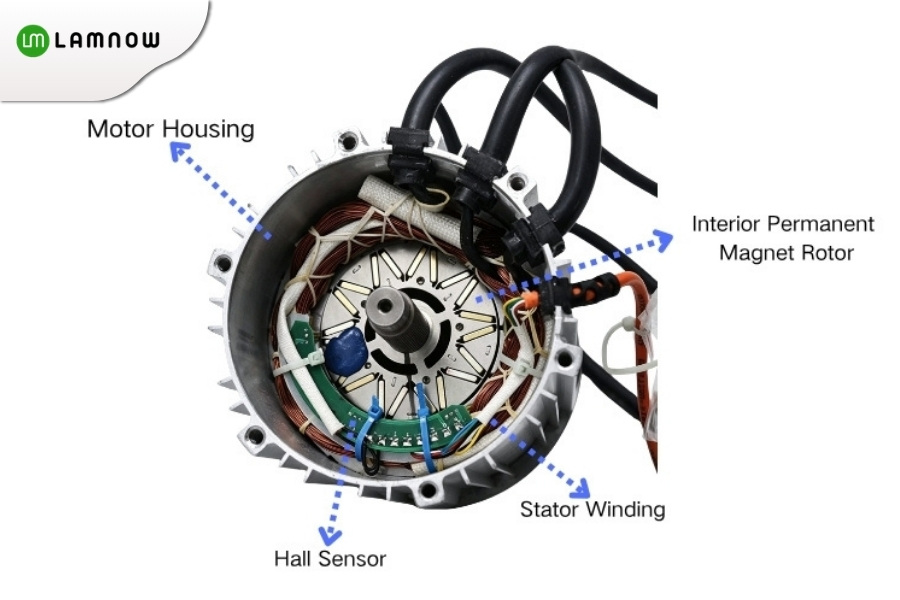
A permanent magnet synchronous motor usually consists of stator windings, a rotor core, and rotor permanent magnets. The permanent magnets can be mounted on the rotor surface or embedded inside the rotor.
Principle
The drive allows the stator to generate a rotating magnetic field, while the rotor permanent magnets remain synchronized with this rotating magnetic field. As a result, the rotor speed is the same as the synchronous speed of the magnetic field.
Features
- High efficiency, especially suitable for variable-frequency speed control applications.
- High power density, allowing a smaller size at the same power level.
- When used with a drive, it can achieve high-precision speed and position control.
- Permanent magnets are relatively expensive.
- Under high-temperature or abnormal operating conditions, the risk of demagnetization should be considered.
Applications
For new energy vehicles, the motor not only needs to deliver sufficient power, but also needs to minimize size and weight as much as possible. Therefore, permanent magnet synchronous motors, with their high efficiency and high power density, offer clear advantages.
Permanent magnet synchronous motors are commonly used in drive motors for new energy vehicles, industrial robot joints, CNC machine tool spindles, variable-frequency air conditioner compressors, and high-end automation equipment. For example, the main drive motor of the Tesla Model 3 is commonly classified as an interior permanent magnet synchronous reluctance motor (IPM-SynRM), while hybrid models such as the Toyota Prius Prime also use permanent magnet AC synchronous motors..
Differences from BLDC Motors
It should be noted that BLDC motors and permanent magnet synchronous motors have structural similarities. Many of them use a rotor with permanent magnets and a stator with windings. In engineering practice, they are usually distinguished based on back EMF waveform, control method, and application conventions: BLDC motors place more emphasis on electronic commutation and square-wave or trapezoidal-wave control, while permanent magnet synchronous motors are more commonly used with sinusoidal-wave or vector control for high-efficiency and high-precision speed control applications.
The motor types introduced above are mainly understood from the perspectives of power supply type and operating principle. In addition to “how the motor rotates,” many applications also care about “whether it can rotate precisely to a required position.” This brings us to stepper motors and servo systems.
Stepper Motor
Structure
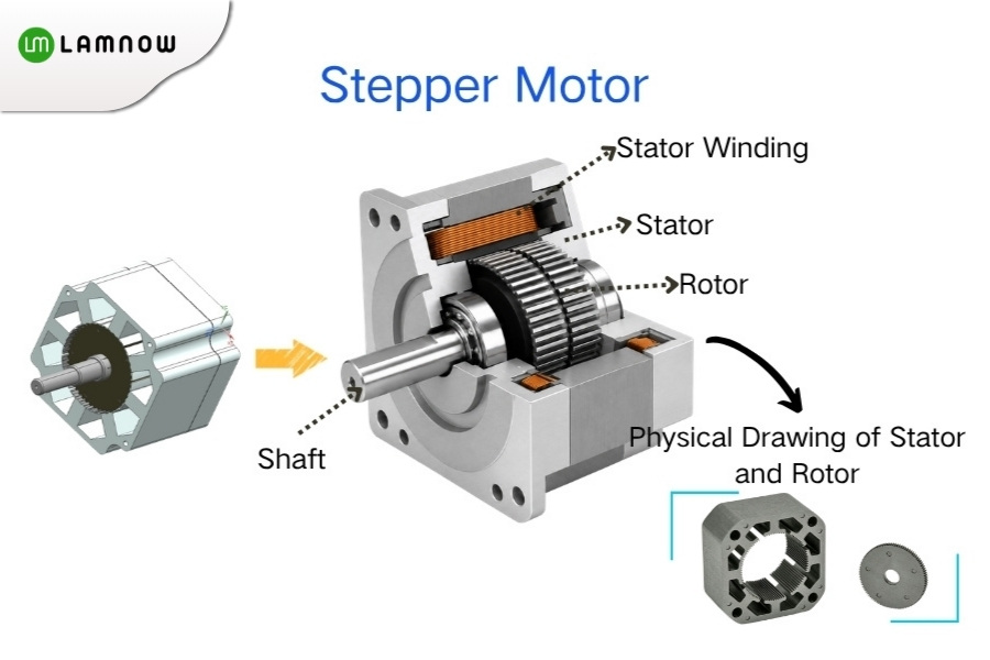
A stepper motor usually consists of a toothed stator, a rotor, and multi-phase windings. In a common hybrid stepper motor, the rotor has fine teeth, and the stator windings are energized in a specific phase sequence.
Principle
For each input pulse, the motor theoretically rotates by a fixed angle, known as the step angle. As long as no step loss occurs, the number of pulses can be used to estimate the theoretical position.
Common two-phase hybrid stepper motors usually have a step angle of 1.8°, which means 200 steps per revolution. This feature makes them widely used in low-cost positioning applications.
Features
- Simple control and relatively low cost.
- Commonly used for open-loop positioning and does not necessarily require a position feedback sensor.
- Good low-speed positioning capability.
- Torque drops significantly at high speeds.
- Step loss may occur under overload or improper acceleration and deceleration settings.
- Operating noise and vibration are usually more noticeable than in servo systems.
Applications
Stepper motors are commonly found around us in home printers, 3D printers, small CNC equipment, desktop engraving machines, optical microscope stages, and low-cost automation equipment. For example, some 3D printers use stepper motors in their feeding and motion mechanisms to achieve low-cost positioning. They can be regarded as a common choice for low-cost precision positioning applications.
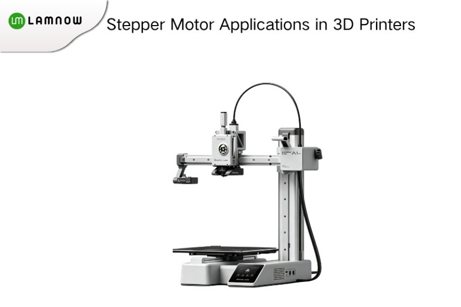
In practical motor selection, many customers ask: should a stepper motor or a servo system be used for low-cost positioning applications? Generally speaking, if the load is not heavy, the speed is not high, and the budget is limited, a stepper motor is more suitable. If high speed, high precision, and long-term stable operation are required, a servo system is a safer choice.
Servo Motor
Structure
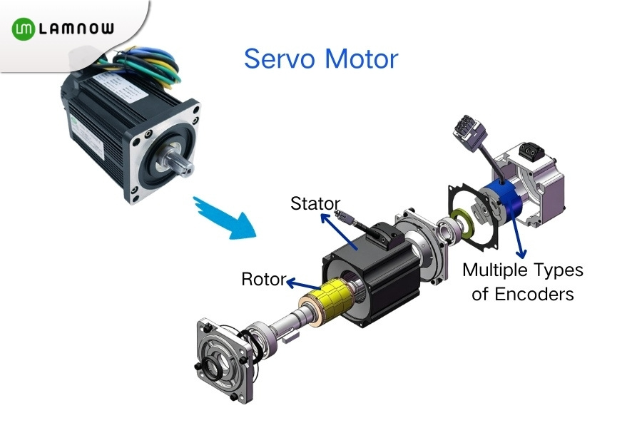
A servo system usually consists of a servo motor, an encoder, a servo drive, and a controller. The motor outputs motion, the encoder provides position or speed feedback, and the drive adjusts the motor operation based on the feedback signal.
Principle
A servo system uses closed-loop control. The controller provides a target position or speed, the encoder gives real-time feedback on the actual state, and the system continuously corrects any errors.
Features
- High positioning accuracy and fast response.
- More stable torque output at high speeds.
- Certain overload capability, suitable for dynamic loads.
- Closed-loop control can detect and correct errors in time.
- Higher cost than stepper motors.
- Higher requirements for tuning and drive control.
Applications
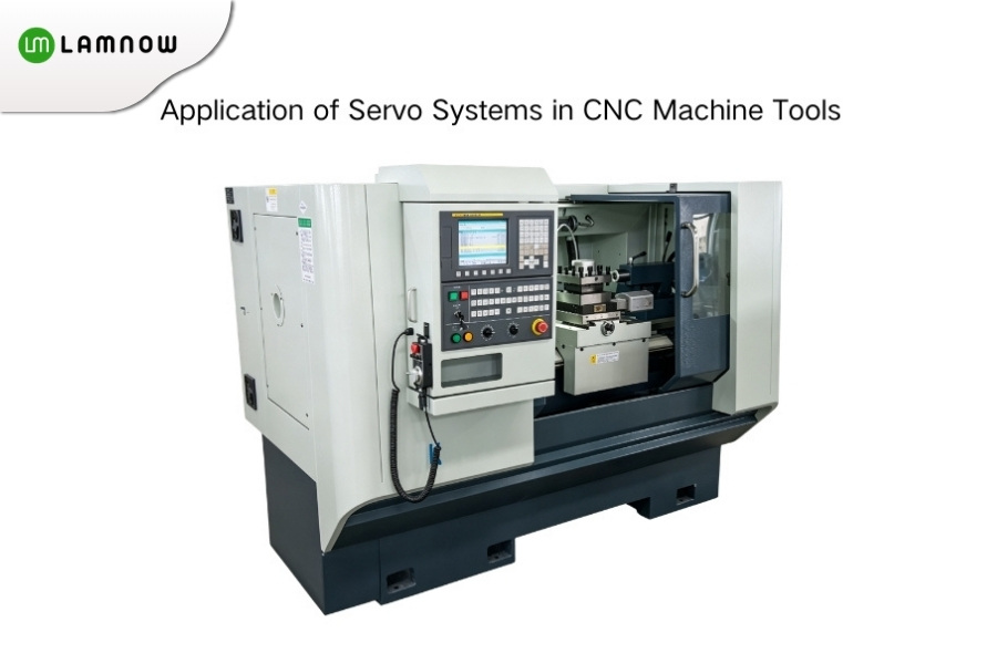
Servo systems are commonly used in industrial applications that require high speed, high precision, and strong stability, such as CNC machine tools, industrial robots, automated production lines, printing equipment, press brakes, and packaging equipment. In these applications, equipment not only needs to “move,” but also to “move accurately, stop steadily, and respond quickly.” Therefore, servo systems are usually more suitable than ordinary stepper motors for high-speed, high-precision, and dynamic-load applications.
Stepper motors and servo systems solve the problem of “how to rotate precisely.” However, some equipment does not need rotary motion, but instead requires a platform to move quickly and smoothly in a straight line, such as laser cutting machines, inspection platforms, and high-speed conveying equipment. This is where linear motors come into play.
Linear Motor
Structure
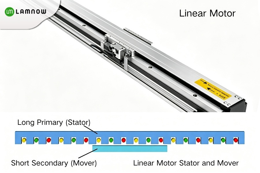
A linear motor can be understood as a rotary motor unfolded along its circumference, forming a linearly arranged stator and mover. Common structures include flat-type, U-channel, and tubular linear motors.
Principle
After power is applied, electromagnetic thrust is generated between the stator and the mover, directly producing linear motion without first converting rotary motion into linear motion.
Features
- Directly produces linear motion.
- Reduces intermediate transmission mechanisms such as ball screws, gears, and timing belts.
- Fast response and capable of high positioning accuracy.
- Small transmission clearance, suitable for high-precision motion.
- Higher cost.
- Higher requirements for drive control, dust protection, and heat dissipation design.
Applications
At present, linear motors are mainly used in high-end applications, such as high-precision CNC machine tools, gantry drives for laser cutting equipment, precision inspection platforms, and maglev trains. As the technology continues to mature, it is gradually expanding into more civilian applications.
Axial Flux Motor
Structure
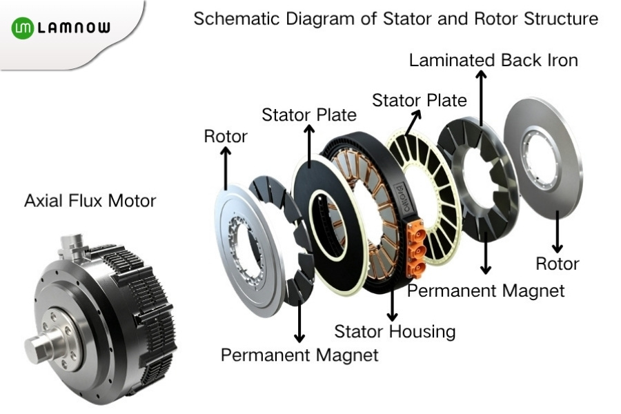
An axial flux motor is also called a disc motor. Unlike traditional cylindrical radial flux motors, its stator and rotor are usually disc-shaped, and the magnetic flux direction is along the motor axis. One common structure is the “rotor–stator–rotor” double-rotor single-stator configuration.
It can be simply understood this way: a radial flux motor is more like “a cylinder inside another cylinder,” while an axial flux motor is more like “a disc facing another disc.” In the former, the magnetic flux mainly travels in the radial direction; in the latter, the magnetic flux mainly passes through the air gap in the axial direction.
Principle
After the stator windings generate a magnetic field, the magnetic flux passes through the air gap in the axial direction and interacts with the rotor permanent magnets to produce torque.
Features
- Short axial length and flat structure.
- Helps achieve higher torque density and power density.
- Suitable for applications with limited space and weight-sensitive requirements.
- Higher requirements for structure and assembly.
- More challenging heat dissipation and air gap control.
- Not yet widely adopted in many traditional industrial applications and passenger vehicle main drive systems.
Applications
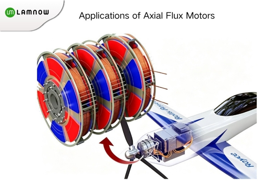
Axial flux motors are mainly suitable for applications with high requirements for size, weight, and power density, such as high-performance electric vehicles, electric aviation propulsion, electric marine propulsion, and high-end robot joints. The Dark Matter motor in the Koenigsegg Gemera, as well as related high-performance Mercedes-AMG models, demonstrate the application potential of axial flux motors in high power density scenarios.
Reluctance Motor
Structure
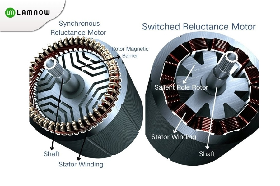
In a broad sense, reluctance motors mainly include synchronous reluctance motors and switched reluctance motors. Their common feature is that the rotor usually has no permanent magnets or rotor windings, and relies on the shape of the rotor magnetic circuit to create differences in magnetic reluctance.
Principle
The rotor tends to move toward the position with the lowest magnetic reluctance. The stator windings generate a changing magnetic field according to a specific pattern, allowing the rotor to keep moving under the effect of reluctance torque.
Features
- Simple and robust rotor structure.
- No permanent magnets, so there is no risk of permanent magnet demagnetization.
- Good capability for high-temperature, high-speed, or harsh operating conditions.
- Relatively controllable material cost.
- Relatively high noise and vibration.
- Higher control complexity and greater requirements for drive algorithms.
Since the rotor usually does not require permanent magnets, reluctance motors can reduce dependence on rare-earth permanent magnet materials, which is also one of the reasons why they have attracted attention in some industrial energy-saving applications.
Applications
Reluctance motors are commonly used in some industrial fans, pump equipment, mining equipment, metallurgical equipment, and auxiliary drives for new energy vehicles. Synchronous reluctance motors are more commonly used for energy-saving drives, while switched reluctance motors are suitable for applications that require a more robust rotor structure.
Shaded-Pole Motor
Structure
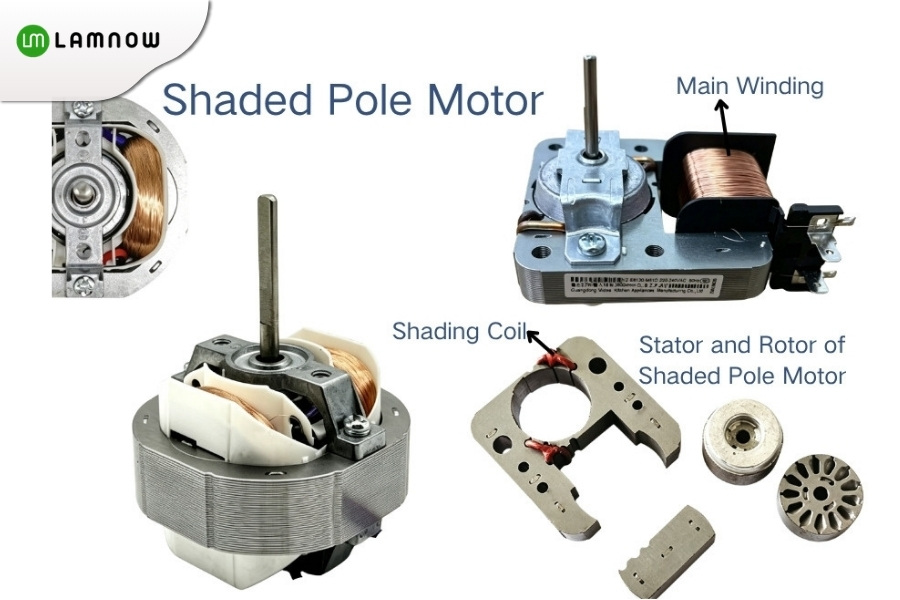
A shaded-pole motor is a very simple type of single-phase AC induction motor. It usually consists of a stator main winding, a shading coil, also called a short-circuit ring, and a squirrel-cage rotor.
Principle
The shading coil causes part of the magnetic flux to lag, forming a weak rotating magnetic field that drives the squirrel-cage rotor to start and run.
Features
- Simple structure with few components.
- Low cost and reliable operation.
- Low starting torque, usually suitable only for no-load or light-load starting.
- Low efficiency and low power factor.
- Usually low power output, not suitable for high-performance drive applications.
Applications
Shaded-pole motors are usually used in low-power, light-load equipment, with common power ratings often in the range of several tens of watts. The focus is not high efficiency, but simple structure, low cost, and reliable operation.
Therefore, they are mainly used in low-power equipment that does not require high efficiency, high starting torque, or advanced speed control performance, such as small fans, exhaust fans, microwave oven turntable motors, and small refrigerator fans.
Different Motors, Different Advantages
Overall, different motors are suitable for different applications. Brushed DC motors offer low cost, while brushless DC motors offer high efficiency. Induction motors are reliable and durable, while permanent magnet synchronous motors provide high power density.
Stepper motors and servo systems are suitable for precise control, linear motors are suitable for linear motion, and axial flux motors are suitable for compact, high-power-density applications. When choosing a motor, the key is not which type is more advanced, but whether it fits the specific equipment.
Which type of motor do you find most confusing in practical applications? Feel free to leave a comment and discuss it with us. In the future, we can continue exploring how to choose the right motor for different applications.