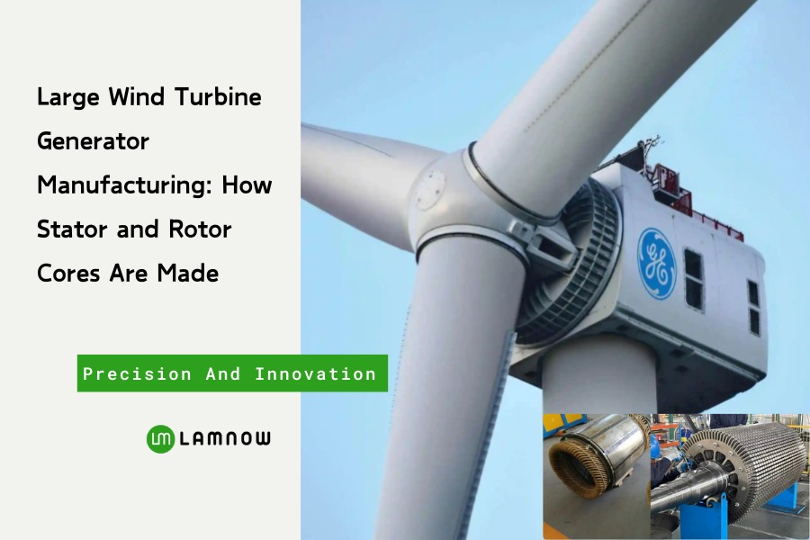
Have you ever wondered how those giant wind turbine generators—standing tall across mountains and coastlines, weighing tens of tons—are actually made?
From electrical steel selection, lamination stamping, coil winding to final assembly and testing, let’s explore how these “mega motors” are born.
Manufacturing Process of Wind Turbine Generator Cores
Selection of Electrical Steel Materials
You might be curious — why do such massive generators rely on thin sheets of silicon steel?
In fact, the quality of electrical steel directly determines the magnetic flux density and core losses.
In large wind turbine generator production, we commonly use high-quality silicon steel coils from Baosteel, Shougang, and WISCO. The standard thicknesses are 0.35 mm and 0.5 mm, with typical grades such as 50W400, 50W470, and 50W600.

Each batch of material undergoes strict magnetic property, coating insulation, and core-loss testing to ensure its magnetic flux density, core loss, and insulation performance meet design standards.
Cutting of Silicon Steel Sheets
The first step is to cut the silicon steel sheets into square laminations based on the outer diameter of the stator and rotor.
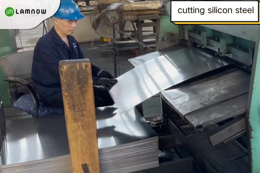
Since the raw coils themselves have dimensional tolerances, each square sheet is rotated 90° before blanking to avoid cumulative errors.

Then, high-tonnage compound punching machines cut the squares into circular sheets, which serve as the base material for stator and rotor laminations.

Laser Cutting
During prototype development or small-batch production, laser cutting is often used to produce stator and rotor laminations.
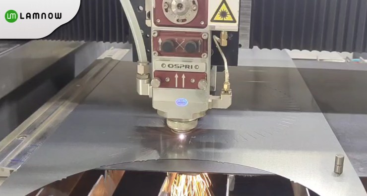
This method requires no tooling and can achieve a precision of ±0.05 mm.
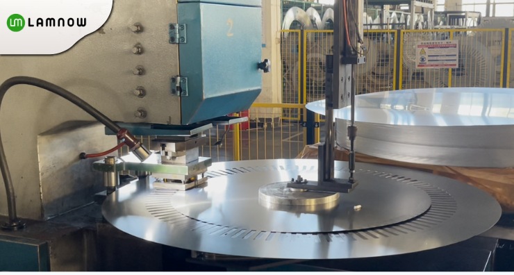
Single-Slot Punching
The circular silicon steel sheet is transferred to a single-slot punching machine, usually servo-driven.
Each press stroke punches one slot shape, and after multiple punches, the stator lamination pattern is completed.
The rotor structure is more complex, having a central shaft hole. Therefore, during compound punching, both the shaft hole and evenly distributed cooling holes are formed. Then, single-slot punching creates the rotor slots.

A complete stator or rotor core typically consists of hundreds or even thousands of laminations.
Segmented Compound Punching
For stators with diameters over 1.5 m, integral stamping is impossible, so a segmented structure is used.

Each stator segment is individually stamped with a compound die, then assembled into a full ring using specialized tooling.
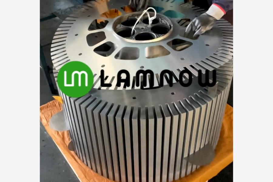
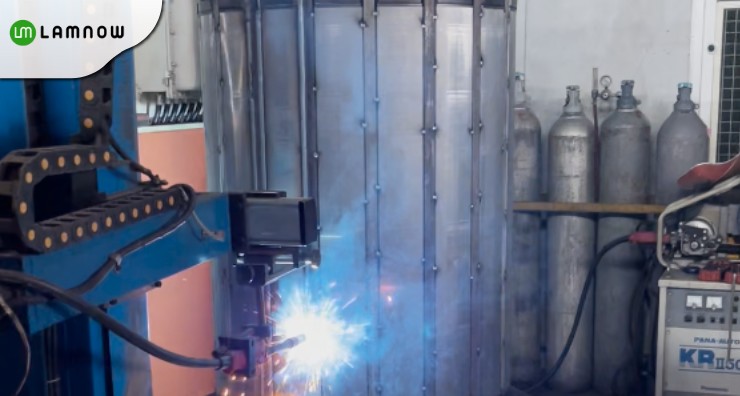
Ventilation Bar Welding
On the rotor laminations, numerous shaped steel bars are welded in a Taiji-like circular pattern to form ventilation ducts for rotor cooling.

Similarly, stator laminations require welding of ventilation bars to create airflow channels.
Rotor Lamination Stacking and Assembly
Before assembly, each lamination is carefully inspected.
For the rotor, qualified laminations are stacked on a fixture. A large rotor may require over 10,000 laminations.
At each stacking point, workers use rubber hammers to ensure tight adhesion between sheets.
Rotor Shaft
The rotor shaft is made of forged steel, stress-relieved by annealing, and then precision-machined.
It is fitted into the rotor core through interference or thermal shrink fitting.

Even with continuous work, rotor assembly can take over three hours.
The finished rotor weighs 4–5 tons and must be lifted using an overhead crane.
Installation of Conductor Bars
Copper conductor bars (about 8 mm in diameter) are inserted from front to back into the rotor slots.
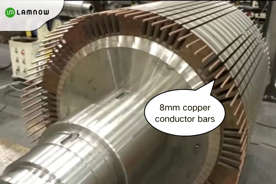
These bars serve two main functions:
Conduct induced currents generated by magnetic field cutting.
Prevent deformation caused by centrifugal forces during rotation, keeping the rotor structure stable.
After precise positioning (within millimeters), the bars are gently tapped into place and secured by TIG welding, completing the rotor fabrication.
Stator Lamination Stacking and Assembly
TIG Welding
Stator assembly is relatively simpler.
Over ten thousand laminations can be stacked within an hour and are fixed by TIG welding.
CNC Machining
The welded stator core is machined on a vertical or horizontal CNC lathe to ensure accurate outer-diameter dimensions.
After grinding and high-pressure air cleaning, a uniform internal magnetic grid structure is formed.

Stator Winding
Large wind-turbine stators often use preformed or rectangular copper-wire windings.
The precision and insulation level of the winding process determine the generator’s long-term stability.
Insulation Materials
The insulation system must withstand high temperature and voltage. Common materials include:
Slot insulation: Nomex 410, DMD composite paper

Turn insulation: Polyester enameled wire or mica tape
Overall insulation: Class F or H epoxy systems
Winding and Forming
Once materials are prepared, conductors are wound into bobbin-shaped coils using a winding machine, then wrapped with heat-shrink tape or waxed cloth for insulation.
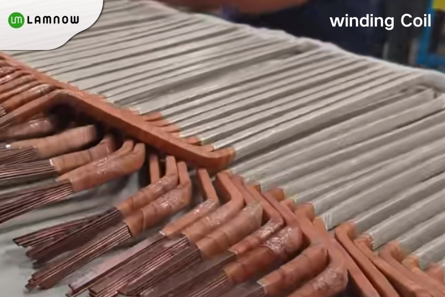
Coils are inserted into the stator slots, and the overhanging coil ends are shaped and tied for secure fixation.
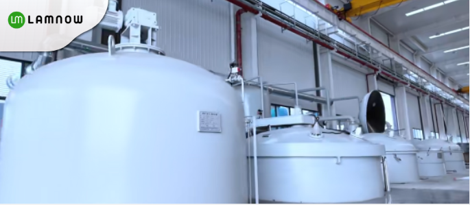
Vacuum Pressure Impregnation (VPI)
After winding, the stator undergoes vacuum pressure impregnation, allowing insulating varnish to fully penetrate gaps between windings.
This enhances mechanical strength and dielectric performance.
Curing is performed at 150–180 °C using Class H varnish.
Final Assembly
Once the stator and rotor are complete, the generator proceeds to final assembly.
Using hydraulic equipment, the rotor is inserted into the stator while maintaining a precise air gap of 2–4 mm.
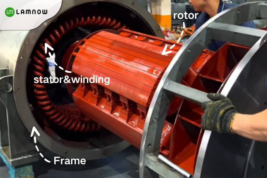
Bearings, cooling pipelines, end covers, and terminal systems are then installed.
Large wind turbine generators typically adopt a closed air-to-water cooling system to ensure stable temperature rise during operation.
Testing and Quality Inspection
Before leaving the factory, every generator undergoes rigorous testing:
Dimensional inspection: Verification of all mechanical tolerances

Electrical tests: Insulation resistance, dielectric strength, and surge test (up to 4 kV)
No-load and short-circuit tests: Measurement of losses and efficiency
Vibration and noise tests: Ensuring smooth operation
Overspeed and dynamic balance tests: Verifying rotor stability
All test data are archived for product traceability and long-term performance evaluation.
From the selection of high-grade electrical steel to lamination, winding, and final assembly, every step reflects the mastery of modern manufacturing and engineering excellence. These massive machines are not just products—they are symbols of innovation driving the world toward cleaner energy.
Large Wind Generator Lamination – Choose Lamnow
we take pride in producing high-quality stator and rotor lamination stacks for wind turbine generators. Whether you need laser-cut prototypes, epoxy-bonded laminations, or full-scale production cores, our advanced facilities and engineering team are ready to support your next renewable energy project.

Contact us today to discuss your requirements and see how our precision manufacturing can power your wind energy solutions.