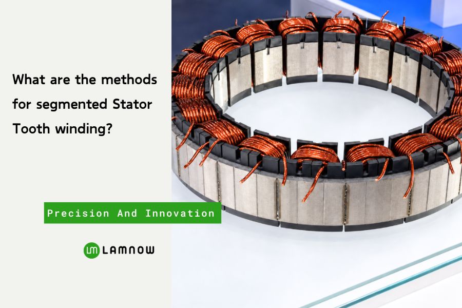
What are the methods for segmented stator tooth winding, and which one best fits your motor design? Segmented stators use separate teeth, allowing simpler insulation, coil placement, and lead control. These methods can improve the slot fill factor.
How Should a Segmented Stator Tooth Be Wound?
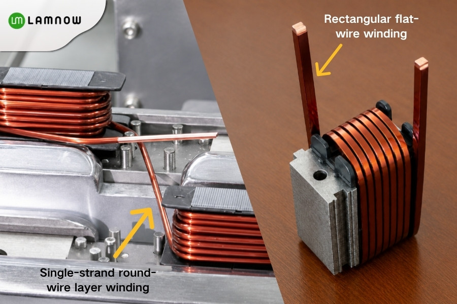
Based on conductor type, segmented stator teeth winding can generally be divided into three categories:
1. Single-strand round-wire layer winding
2. Rectangular flat-wire winding
Single-Strand Round-Wire Layer Winding
Single-strand round wire is one of the easiest winding solutions to implement for small, middle-segmented stators.
Bare copper diameter: 0.6–1.45mm
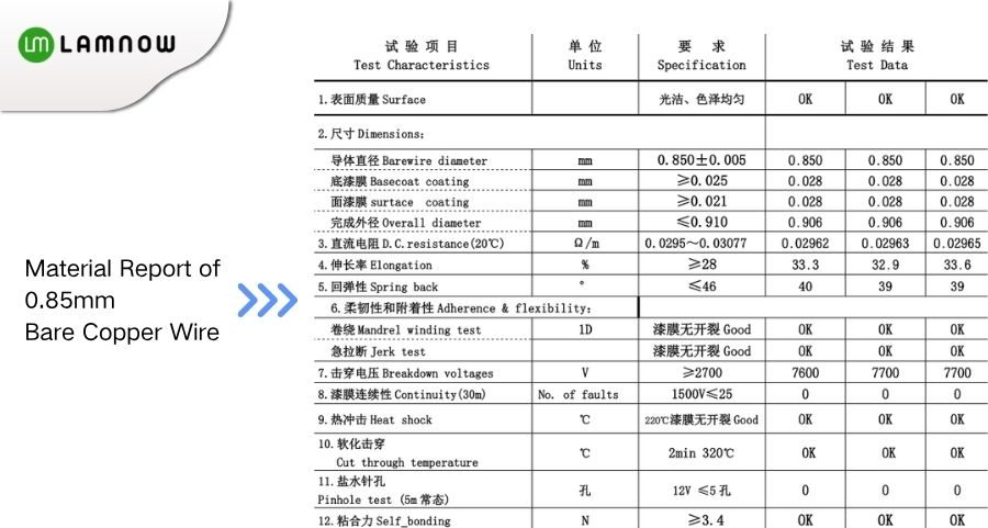
Recommended wire: Grade 2 enamelled copper wire
Thermal class: Class 180 or Class 200, depending on the motor temperature requirement
Winding Process
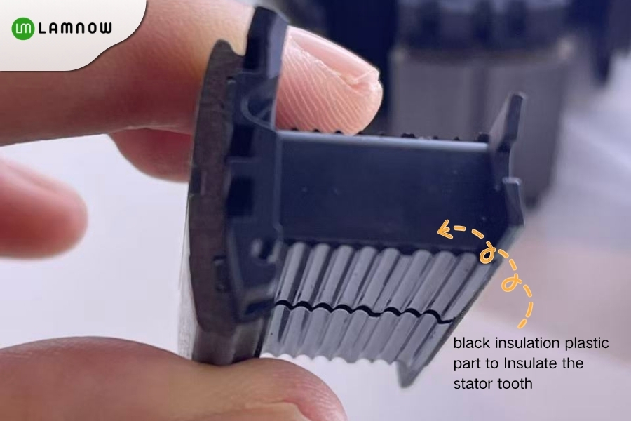
Step 1: Insulate the stator tooth
Install an insulating plastic part or apply slot insulation, slot-mouth insulation, and end-face insulation to the individual tooth.
Step 2: Clamp the individual tooth
Mount the stator tooth in a dedicated rotating fixture.
During winding, either the tooth itself rotates or a flyer or wire guide moves around the tooth. The fixture must maintain the tooth position accurately and prevent movement during acceleration and deceleration.
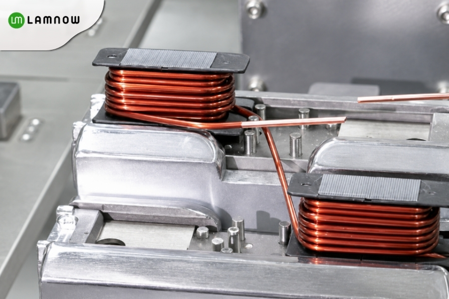
Step 3: Wind the Stator Tooth
The first conductor layer should be placed sequentially along the insulating bobbin or slot wall. After completing the first layer, the wire is arranged in the opposite direction to form the second layer.
The quality of the first layer directly affects the remaining layers and the final coil dimensions. The conductors should not cross, overlap randomly, or change direction sharply at the slot opening.
Step 4: Control the coil-end height
After winding, mechanical forming or low-pressure thermal forming may be used to stabilize the coil shape. However, excessive pressure must be avoided because it can damage the enamel insulation.
Step 5: Secure the lead wires
The starting and finishing leads should be reserved according to the three-phase connection design.
Step 6: Test and assemble the wound segments
After winding, each tooth can be tested individually before the complete stator is assembled.
Typical inspections include:
- DC resistance
- Number of turns
- Inductance
- Insulation resistance
- Surge or turn-to-turn test
- Withstand-voltage test
- Coil-end height
- Lead-wire position
The wound teeth are then assembled into a complete stator. The star or delta connection, busbar welding, impregnation, and final electrical testing are completed afterward.
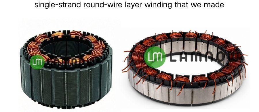
Round-wire winding for segmented stators is widely used in garden tools, handheld floor-cleaning machines, automotive water pumps, low-power industrial servo motors, elevator motors, and other compact motor applications.
Rectangular Flat-Wire Winding
When the project requires a larger copper cross-section, shorter coil ends, more repeatable conductor positioning, or improved utilization of the winding window, rectangular flat wire may be considered.
For a segmented stator, commonly used conductor sizes:
- 1.0 × 0.5 mm
- 1.2 × 0.6 mm
- 1.5 × 0.8 mm
- 2.0 × 1.0 mm
- 1.7mm × 2.5 mm
A rectangular-wire specification should clearly define:
Bare copper width * Bare copper thickness
Maximum finished width after enamelling * Maximum finished thickness after enamelling
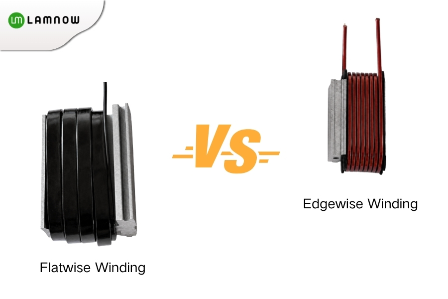
Based on the winding method, stator tooth flat wire winding can be further divided into Flatwise Winding and Edgewise Winding.
Flatwise Winding
In flatwise winding, rectangular wire is stacked on its wide face, like layers of flat copper strip. This suits regular single-tooth coils or preformed coils. However, designers must coordinate coil buildup direction with slot width, tooth height, and end-winding space.
Edgewise Winding
Edgewise winding uses the narrow edge as the main stacking direction, with the wide face nearly upright. It can reduce the coil size in one direction. However, the conductor bends along its stiffer axis. This increases the risk of springback, corner bulging, cross-sectional distortion, and enamel damage.
Edgewise winding therefore usually requires dedicated guiding, forming, and clamping tools. Neither method is universally better. The right choice depends on tooth geometry, slot space, and coil bends.
These points mainly cover conductor selection for radial-flux segmented stators.
Most axial motor stator segmented tooth use a flat winding process.
YASA’s stator main features are the yokeless segmented stator structure and automated rectangular-wire winding.
YASA eliminates the conventional continuous stator yoke and divides the stator into individual pole pieces, or segmented teeth. These segments are formed from soft magnetic composite (SMC) material. This design reduces weight, avoids magnetic saturation in the stator yoke, and allows each stator tooth to be wound independently before final assembly.
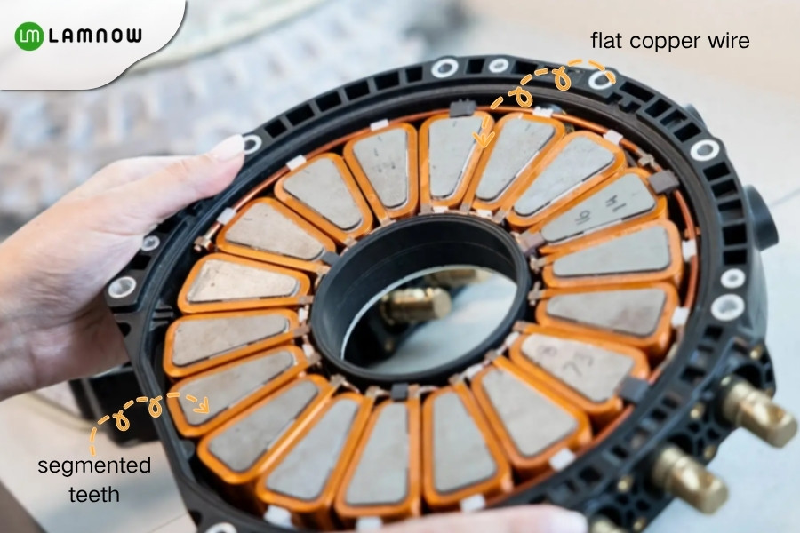
The stator coils are wound using flat rectangular copper wire. Compared with conventional round wire, rectangular wire can significantly improve copper utilization within the winding space, with a net copper fill factor of more than 60% under suitable design and manufacturing conditions. This allows more copper conductor to be accommodated within the same volume, reducing copper losses and substantially increasing torque density.
How Should You Choose the Right Method for Your Project?
For a new segmented stator project, evaluate the options in the following order:
- First, confirm whether the design uses a radial-flux or axial-flux structure.
- Then choose round or rectangular wire based on coil shape, current requirements, and adjustment needs.
- For rectangular wire, determine whether flatwise or edgewise winding better matches the tooth geometry and end-winding space.
- Finally, choose direct winding, preformed-coil assembly, or chain-stator continuous winding based on the prototype, pilot-production, or mass-production stage.
Round wire generally offers greater flexibility, while rectangular wire demands more precise dimensional design and forming capability. Individual modules suit prototype adjustments, while chain winding better suits stable designs and high-throughput mass production.
Lamnow- Segmented Tooth Winding China Manufacturer
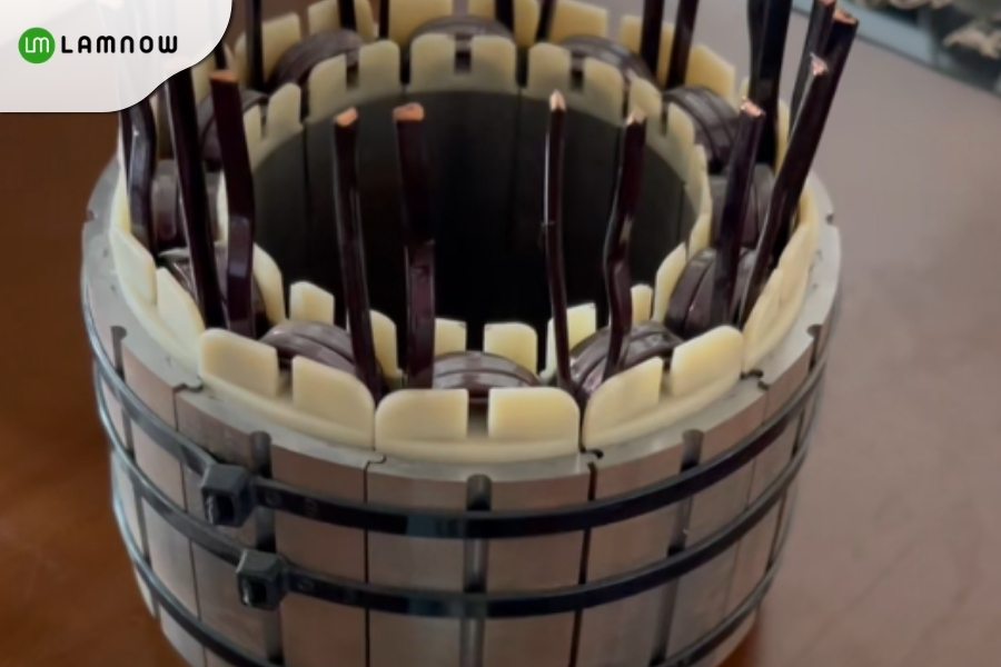
Looking for a reliable segmented stator winding partner? We provide both round-wire and rectangular-wire winding for segmented stator teeth, supporting axial-flux stators, servo motors, frameless torque motors, and other high-performance applications. Send us your drawings and winding requirements to discuss a practical manufacturing solution.